The hot wire mystery
I like to build my prototype electronic circuits on perf- or stripboard after having tested it on a breadboard. Actually I would have loved to have breadboards around when I started with electronics some 25 years ago, but it was not before the late 1990s that I got familiar with this tool. or most circuits I prefer the version of stripboard which is known as TriPad because of the groups of three neighboring pads which are connected together, isolated from the next group.
In order to connect signals over wider distances on these boards I either use non-insulated wire bridges which I form from cut-off component legs and plated copper wire, or a thin PTFE-insulated wire. The insulation of this wire does not melt when you touch it with the soldering iron, which means that you can route the wire quite close to solder junctions and other components’ legs without causing any unwanted connections.
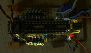
I recently constructed a digital clock with analog voltmeters as display for hours, minutes and seconds. The heart of this clock is an Atmel AVR ATmega88 and I plan to write another post soon on the design itself. For this circuit I used the black insulated wire which I found on a spool, discarded at my workplace. I know I should have been suspicious…
I put everything together and it almost worked directly from the start. But I had problems with the manual controls. Since I shared the ISP pins with the i/o functions of my user interface I used external series resistors in combination with the internal pull-up resistors in the AVR processor. And sometimes everything worked, and sometimes it didn’t.
It also took me a while before I even considered the actual cause of the problem. Before I changed the code several times because I thought there might have been a bug in the way I addressed the i/o pins – even though I really couldn’t figure out how this could have happened.


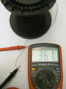
Actually, there seems to be an outer layer on the insulation which is somewhat conducting. This conductivity can be reduced by cleaning the wire with some alcohol. However, since I’m not sure whether this was an indication of the insulation breaking down or a contamination of the wire I decided to retire the whole spool back to where it came from… probably there was a reason for the last person to throw it away anyway…

