A couple of years ago I presented a preamplifier on my homepage which allowed it to use standard oscilloscope probes on the line input of a soundcard. This small circuit solved the problem that a soundcard has quite a low impedance on its line inputs which makes it unusable for measuring high-impedance signals.
Already at that time I found quite a few application programs to use the soundcard as a simple and cheap storage oscilloscope, but nobody seemed to bother about the impedance issue or any way to connect oscilloscope probes to a soundcard.
My previous design used a single-supply operational amplifier and a 9 V battery to offer a standardized input impedance of 1 MΩ at the input and buffer the input signal which is then capacitively coupled into the line input of a soundcard. A directly coupled signal would have required a surgical procedure on the soundcard itself, which I deemed too risky.
Now, you can buy external USB soundcards for cheap money and about a year ago I got the idea to modify such a card for a DC connection of the input signal. In 2008 also the electronics journal Elektor took again up the idea of using the soundcard for electronic measurements. So now I finally went all the way and designed a universal input/output circuitry which can be adapted to different soundcards and offers two input channels with a standardized input impedance of 1 MΩ and two low-impedance, DC connected output channels which can drive an amplitude of 1 V into a 40 Ω load.
The USB soundcard
My design is based on the USB soundcard SC-5500P from Trust which is based on the CMedia USB sound chip CM106. From the datasheet of this chip you can see that it uses a single +5 V supply voltage and handles negative amplitudes of sound signals by offsetting these with a reference voltage of +2.25 V which is available on pin 38 of the QFP100-package for the connection of external bypass capacitors.
In order to connect a signal to the inputs of this chip without coupling capacitors you have to add this reference voltage to the signal, when taking the output signal you would have to subtract this voltage from the signal – this can easily be done with operational amplifiers.
The 5.1 soundcard comes with 2 stereo output channels, 1 mono output channel, 1 stereo line-in channel and 1 mono microphone input channel (the chip itself actually supports stereo microphone input, but this is not externally available).
Supply voltage
Since the soundcard itself is powered from USB, a single +5 V supply voltage is available on the card. Also the current which can be drawn from this supply is limited, but since I am only adding a handful of operational amplifiers and limit the output current from the signal output this is not a problem.
In order to work with directly coupled positive and negative signals, a negative supply voltage is needed. I chose to create this supply voltage with a small DC/DC converter based on the MC34063 chip.
A first also showed that it was necessary to buffer the reference voltage from the sound chip itself, because the sound chip was not able to drive the four inputs where I needed the reference voltage (one for each input channel and one for each output channel). Therefore I had to add a voltage follower based on a single operational amplifier.
So here is the schematic diagram for the supply part:

(The gray components are original parts on the sound card.)
The input circuit
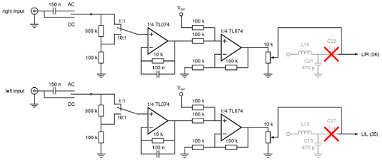
The input circuit consists of a voltage follower with an input impedance of 1 MΩ followed by a voltage adder which takes the 2.25 V reference voltage from the soundcard and adds it to the input signal. This way a symmetric sine wave with an amplitude of 1 V would be transformed into a sine wave swinging between 1.25 V and 3.25 V which is then fed into the sound chips analog-to-digital converter inputs. All the conversion for both channels is performed in a single quad operational amplifier package. I chose the TL074, but for this application the exact type of operational amplifier is not critical. The total amplification of the two stages is 1 – i.e. the input signal is presented to the sound chip with unchanged amplitude. At the very input you can easily implement an attenuator as found on conventional oscilloscopes, allowing you to take only 1/10 or any other fraction of the input signal – I realized a selectable 1/10 attenuation in this circuit.
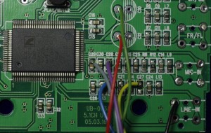
In order to connect it to the soundcard with no interference with the original input circuitry I removed the coupling capacitors (C22 and C27, SMD 3 μF) and soldered the connection cable to one of the solder pads of these capacitors.
Here is the schematic diagram for the input circuit:
The output circuit
Apart from an oscilloscope a signal generator is also a very important tool in an electronics workshop. And some soundcard oscilloscope software also provides means to send output signals to the soundcard, emulating a signal generator. Again the original output circuit of a soundcard might not be up to the task and especially its specifications are almost certainly unknown.
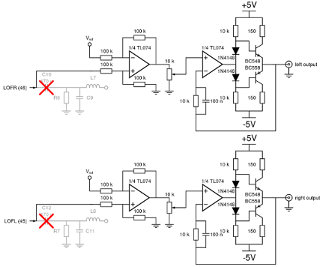
I therefore even designed an output stage. It also consists of two operational amplifiers per channel – one to subtract the 2.25 V reference voltage from the sound chips output signal, and the second one to drive a complementary pair of bipolar transistors. This is not a real power amplifier and the signal amplitude is limited to the actual output voltage of the sound chip, since the two operational amplifier stages have an amplification of 1. But it is able to drive a signal with a 1 V amplitude into a standard 50 Ω load with low distortion.
In order to connect it to the soundcard, I removed the original coupling capacitors (C10 and C12, 470 μF through-hole) and attached wires to one of these capacitors pads on the circuit board.
Here is the schematic diagram for the output circuit:
Putting it all together
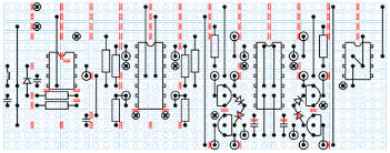
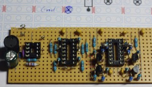
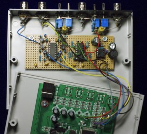
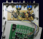
I built up the circuit on a piece of stripboard small enough to fit into a box together with the circuit board of the soundcard. In order to optimize the design I first drew the layout in XCircuit and then soldered it together starting with the wire bridges. The layout on the stripboard looks like this:
Software
There seem to be several applications around on the internet, which can use the soundcard as an oscilloscope. Earlier I was advertising a program called audioTester from http://www.audiotester.de/ on my homepage. It also has seen an upgrade in the recent years, but I haven’t tested it again, yet.
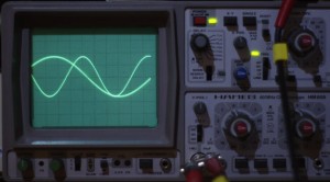
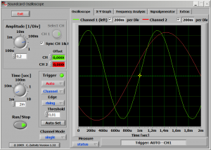
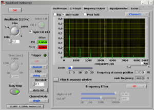
Recently I found another program from Germany, Soundcard Oscilloscope from http://www.zeitnitz.de/. This program allows to control the soundcard output as quite a versatile signal generator, including a noise source, frequency sweep and adjustable phase delay between the two channels. It offers a two channel scope display with cursors and various trigger settings, an independent X-Y display and a spectrum analyzer. It also allows to highpass/lowpass/bandpass/notch filter the input signal and display the result on the scope screen.
The Soundcard Oscilloscope software is free for private and educational use, but I chose to register my copy of the software and plan to contact the author soon with some additional suggestions, but also some flaws which I think I have discovered.
Cost
| part | supplier | price/piece | sum |
|---|---|---|---|
| USB sound card | Kjell & Co. | SEK 299 | SEK 299 |
| plastic box | Kjell & Co. | SEK 69 | SEK 69 |
| stripboard | Kjell & Co. | SEK 45 | SEK 45 |
| TL074 | Electrokit.se | SEK 10 | SEK 20 |
| TL071 | Electrokit.se | SEK 6 | SEK 6 |
| MC34063 | Electrokit.se | SEK 15 | SEK 15 |
| BNC socket | Electrokit.se | SEK 8 | SEK 32 |
| switch | Electrokit.se | SEK 6 | SEK 24 |
| capacitors, resistors, diodes, transistors | own stock | SEK 50 | SEK 50 |

Hi! I saw your blog at Google and have learned a lot from it. Thank you very much for the useful and detailed posts. Will be coming back soon.
I uncovered your blog utilizing google and I must say, this is among the best nicely written articles I’ve seen in a lengthy time. I have bookmarked your web site for further posts.
If you don’t mind me asking, what exactly are you using to prevent junk comments? I noticed your blog is good and free from all the spam bots leaving comments. I have got another site myself, and I just like to keep comments open so I don’t have to come on and approve them all the time, however the spam plugins I’ve tried out are generally failing to prevent even the most obvious and basic spam responses. Is there something good out there that does a good job or is my only hope to keep them moderated or simply just close them all together? Thanks
I am moderating….
So please ALL: stop spamming, your spam will not be posted here…
Uwe.
Thank you for sharing this nice article. I am still confused with RSS 1.0 or 2.0, how do you know the difference? Ineed a good RSS for my blog but it accept only 2.0 feed, is yours a 2.0?
I don’t know the difference between RSS 1.0 and 2.0, but the WordPress installation I am using uses RSS 2.0 feeds.
I have to point out my affection for your generosity in support of persons that have the need for guidance on this important concept. Your very own dedication to passing the message up and down ended up being definitely beneficial and have in every case empowered individuals like me to get to their pursuits. Your personal informative hints and tips indicates a great deal a person like me and especially to my mates. Thanks a lot; from each one of us.
This can be a smart blog. I mean it. You have so a lot knowledge about this issue, and so significantly passion. You also know the best way to make folks rally behind it, obviously from the responses. Youve got a design here thats not too flashy, but makes a statement as large as what youre saying. Excellent job, indeed. wajadud555
‘”‘ I am very thankful to this topic because it really gives great information ;,~
Took me time to read some the comments, however I actually enjoyed the post. It proved to be quite beneficial to me and I am positive to all the commenters right here! It’s always good when you can not only be informed, but also entertained!
Thank you for sharing this nice article. I am still confused with RSS 1.0 or 2.0, how do you know the difference? Ineed a good RSS for my blog but it accept only 2.0 feed, is yours a 2.0?
Nice post. I was checking constantly this blog and I am impressed! Extremely helpful information specifically the last part 🙂 I care for such information much. I was looking for this certain info for a long time. Thank you and good luck.
Oh my goodness! an amazing article dude. Thank you Nevertheless I am experiencing subject with ur rss . Don’t know why Unable to subscribe to it. Is there anybody getting similar rss problem? Anyone who is aware of kindly respond. Thnkx
Great post. Continue to keep more interesting publications. Been following blog for Three days now and I should say I am starting to much like your post. I need to know how can I subscribeto your blog?
My plots would suggest that you shuold run the LIN out settings on the K3 as high as you require to drive your soundcard correctly. The amount of distortion present on the lin out does not seem to increase as the output level is turned up on my K3, it actually decreases.Ghosts on the waterfall shuold be dealt with by choosing an appropriate filter and filter centre frequency as well as setting the dynamic range of your waterfall appropriately.Your mileage may vary and each setup is different.
This is a smart blog. I mean it. You have so much knowledge about this issue, and so much passion. You also know how to make people rally behind it, obviously from the responses. Youve got a design here thats not too flashy, but makes a statement as big as what youre saying. Great job, indeed.
Thank you for an additional fantastic blog. Where else could one get that sort of information written in such an ideal way? I have a presentation that i’m presently functioning on, and that i are probing for such information instead.
Magnificent beat ! I wish to apprentice while you amend your site, how can i subscribe for a blog site? The account helped me a acceptable deal. I had been tiny bit acquainted of this your broadcast offered bright clear idea
It might sound weird but my browser does notseem to be capable to d isplay your article rightly?- It looks like a whole chunk of if just isn’t accurately d isplayed plus the layout from the page does notappear to be ideal. Are you able to confirm that th is publish continues to be set up for Opera?
I have no problem with the display on Opera….
When I click on your RSS feed it gives me a page of weird text, is the malfunction on my end?
Thanks for taking the effort and time to write down some issue that is particularly beneficial
Great post, thanks for sharing. Keep up the fantastic work and keep em coming
Great blog, Just wanted to comment that i can not connect to the rss stream, you might want install the right wordpress plugin for that to workthat.
I have really enjoyied reading your well written article. It looks like you spend a lot of effort and time on your blog. I have bookmarked it and I am looking forward to reading new articles. Keep up the good work!
hey there and thank you for your info – I’ve certainly picked up something new from proper here. I did then again expertise a few technical issues the usage of this website, as I experienced to reload the website lots of instances prior to I may get it to load properly. I were brooding about in case your web hosting is OK? Now not that I’m complaining, however sluggish loading circumstances instances will often have an effect on your placement in google and can harm your quality score if ads and ***********|advertising|advertising|advertising and *********** with Adwords. Anyway I’m adding this RSS to my e-mail and can glance out for a lot more of your respective intriguing content. Make sure you update this once more very soon..
I wish more people would write blogs like this that are really fun to read. With all the fluff floating around on the net, it is rare to read a blog like this instead.
I think this is among the most vital information for me. And i am glad reading your article. But wanna remark on few general things, The web site style is wonderful, the articles is really excellent
Excellent read, I just passed this onto a colleague who was doing a little research on that. And he just bought me lunch because I found it for him smile Therefore let me rephrase that: Thank you for lunch!
Interesting Pictures! I’m a photographer (SG3 Photography, based in Siloam Springs, AR) so I enjoy seeing these kinds of photo’s. Keep up the good work!
This looks to be a very active site. How do you manage to keep up with approving all the comments?
…well, I do for now…
I live in the Twin Cities (Minnesota) I’ll build a home, and i also am wondering of becoming environmentally friendly, I will most likely not perform some of the “ecologically friendly things” like employing all reused elements, or even bamboo floorboards, but more so, radiant flooring heating, all Energy Star appliances (even getting an LED TV), Tankless hot water heater, french drain standard water collection (for water the garden) LED lamps, spray foam insulation etc. Will it be the better choice to get solar energy panels? I recognize that constructing rather of shopping for will save me 15% but really going complete alternative costs over 45% extra.
Hi,
thank you for the great article. I find it extremely useful and also have a couple of technical questions about the scope. First, what are the specs of the scope – do you know what is the effective sampling rate and the effective resolution you get? If I understand it right, in 1:1 mode you can analyze a signal from -2.25V to +2.25V, i.e. 0-5V input and in 1:10 -22.5V to +22.5V. And furthermore, is the USB port protected from the input circuit, for example if you lift the ground from the BNC or have a faulty BNC connection?
Thank you for the reply in advance!
Best regards!
Hi Danail!
Thanks for your questions, of course the bandwidth depends mostly on the specs of the USB soundcard. Many soundcards have several anti-aliasing filters – not only the ones which I deactivated by bypassing L13/C13 and L14/C21. Also the sampling rate is limited by the specs of the soundcard, the highest sampling rate usually found on soundcards is 96 kHz. You should not expect to get a 3dB bandwidth above 40 kHz. Today the sampling depth is usually 16bit, i.e. the resolution is about 75 µV per bit at best, but 24bit soundcards are available…
When it comes to protection: forget it! The USB port itself is one of the safer connections on a normal PC, but when you apply a high enough voltage you will at least blow the USB port, but I can imagine that you can blow up your computer. You should also observe that the ground level of the soundcard is not isolated from the ground level of the PC and most likely also connected to the ground-earth (PE) of your power line.
I liked your circuit but found it limiting. I have a CRT scope for genral use but having a laptop scope is handy when out and about. The laptop sound card is AC coupled on line. What I needed was an attenuater/amplyfyer to increase the range from 0v to 500v.
By using a 12 way 1 pole switch and a resister chain on the input inplace of your 2 way switch for 1:1 or 1:10. I also wanted to amplify realy small voltages so I on the second stage amplifier I have a 2000 times amp I replaced your two 100k resisters with a 2M (across -ve and O/P) and 1K (from -ve to Vref/2 input ground). The input ground has to be Vref/2. Vref (USB 5v) of course being the Amp supply and 0v (USB 0v)
Two final safety features an additional 1M in front of resister chain (divides voltage by 2 hence 2000 amp). and a diode from the first amp +ve input to Vref, this ensures the input voltage is never above 5v, if 12 way switch in the wrong position. I also found the no need for the 100k resister from vref to 2nd amp +ve.
I intend to put all the information on my own website at a later date Many tanks for you post it saved me alot of work
Thanks for your description! I’m looking forward to see your posting on your website!
Uwe.
I Have written an instructable and published this for now http://www.instructables.com/id/0-to-500v-Sound-Card-Osciloscope-and-probes-Cost-P/
I hope you find this usefull/interesting
Why not try to use video capture device for high frequency sampling? Do you ever think about it?
Sure – you can use video-ADCs for high-speed sampling and I planned something like this over 20 years ago. However, at these speeds also the analog frontend gets more demanding.
When it comes to a dedicated video capture device the main problem is the synchronization, because these devices are built to extract the video information (chroma + luma, ord RGB and sync) from the analog video signal.
I presented this project, because I think that an oscilloscope is one of the essential instruments for electronics on any level. The available bandwidth of a sound card is enough to cover a lot of needs – for higher frequencies I myself use a commercial 50MHz analog CRT oscilloscope and in my own projects I had so far never the need for anything faster than that.
I’m dubious on the true aognulae spectrum analyser vs the FFT. All the diagrams you have drawn can be done just as well with DSP. I get the point that FFT will be way slower to produce but if a frequency domain spike is so short you are just as likely to miss it on a true spectrum analyser. Catching stuff like that is much more about triggering than aognulae vs digital. I guess the other issue is it’s much easier to capture a much wider spectrum with an aognulae analyser but that’s another arg,
I think you are comparing two completely different price ranges here. Of course a professional analog or DSP spectrum analyzer is largely superior to what you can achieve with a cheap software FFT combined with a cheap USB soundcard. However, a DSP spectrum analyzer is most probably not affordable for the hobbyist. And the hobbyist might probably not need its added features and possibilities.
Really great job, best grussen, gh65jk89kl65
This schematic could be used on a normal soundcard?
Yes, sure it can.
You need to identify the corresponding input and output pins of the integrated circuits, but otherwise there is no difference between an USB sound card and a traditional one. However, since the traditional soundcard has been on the verge of extinction for quite a while now, the functinality will most often be found in some corner of the mainboard instead. This involves the risk of soldering and operating on your mainboard and if you are not sure what you are doing and how you are doing it, there is a risk of permanently damaging your whole computer.
Thanks!I have an old creative 5channels,i have to find the inputs and outputs on the main cip?bypassing the rest of the components?
In order to allow DC signals you will need to bypass all additional input circuitry, which mostly consists of a capacitor as high-pass filter. If you are only interested in AC signals in the standard range of the sound card you can use a simpler circuit like this older post of mine.
Uwe.
The idea of the sound amplifier as a sound card has been very helpful for me. I am using this as a preamplifier. The way you described the entire hardware and the circuits was very informative for me. The detailed description of the software part was also very much helpful. Hats off to you guys.
Great article. I have the same sound card. I wonder if your design would allow me to view very low sine frequency. Say between 0.01 and 1 Hz. What is the lowest practical sine frequency it can handle?
Thanks
When you bypass the coupling capacitors there is absolutely no lower frequency limit. The scope software by Zeitnitz has a lowest setting of 10 sec per div.
Thanks for a great article, all very clear and easy to understand.
I’ve started building one of these and come across a problem with your -5V supply circuit. As shown it will not work, because the 100k current sampling resistor on pin 7 of the MC34063 is far too big. It needs to be less than 1 ohm! The 150nF capacitor that sets the oscillator frequency is also too high, it should be nearer to 470pF. With these values my circuit works just fine.
Hi Mike – and thanks for your comments!
You are absolutely right about the resistor and the capacitor. You are the first to comment on these obvious mistakes from my side and I can assure you that these are merely typos. If you look at the photo of the circuit board, you will see the socket for the MC34063 to the far left. There you can see that I use a wire bridge instead of the resistor between Vcc and pin 7 – this will disable the over-current protection of the chip, but it works nonetheless. And the capacitor in my circuit is actually 150p and not 150n.
When it comes to the MC34063 I find this online-tool quite useful: http://www.nomad.ee/micros/mc34063a/index.shtml
I have built the circuit and got it working, and wondered how you calibrated yours? I measured an RMS voltage using a multimeter then tried to set the scope to the equivalent pk-pk value. The Windows volume control is too coarse, and the 10k pot feeding the input to the sound card doesn’t work very well. As the wiper leaves the top of the pot the sound card stops responding (possibly because the op amp output impedance has risen?). Any tips here please?
Be careful with ac multimeter measurements – the frequency range of digital multimeters is normally quite poor and if your signal is not around 50-60Hz I would not trust the multimeter to read the correct rms voltage at all.
I myself have the luxury to own a “real” oscilloscope for comparison, otherwise I would recommend you to build a simple 1kHz (or so) square wave oscillator, e.g. from an NE555. It should give you a peak-peak voltage equal to the supply voltage of the NE555 which you can use for calibration.
About the sound card not reacting to the pot unless it is at its “top” position: what kind of pot did you use? The regular input impedance of the sound card should be 10kohm or higher so with a 10kohm pot as in my drawing the change in output impedance of the driving opamp should not have such a consequence. At mid-position the output impedance of the driving stage has reached its maximum value with (5kohm parallel 5kohm) plus the opamp’s output impedance of about 100ohms, i.e. about 2.6kohm. Yes, this gives an additional attenuation leading to a non-linear behavior of the pot-setting, but this non-linearity is less than 20%. Could there be a different reason for this behavior of the pot in your circuit?
OK I’ll use a lower frequency with the multimeter (or even dc from a battery?). The pots I used were 10k presets but I’ve taken them out now and can get by without them. I’m very pleased with your design and have already used it to diagnose and repair a vintage CD player!
Do you think that i can mod this usb sound card?
It mount CM106 chipset:
http://www.ebay.it/itm/SCHEDA-AUDIO-7-1-CANALI-USB-ESTERNA-VIRTUAL-3D-SOUND-ADATTATORE-/280802336155?pt=Schede_audio_per_PC_e_Server&hash=item41611f9d9b&_uhb=1
Hi Matteo,
my Italian is not very good, but most compact USB sound cards I have seen so far only have a mono microphone input, even though most chipsets support stereo inputs. Another problem will be that this card probably is very compact on the inside – it might not be easy to do the soldering. On the other hand, for just EUR 4.40 it might well be worth a try!
The CM106 chipset itself supports both stereo microphone and stereo line inputs. You would need to use the line inputs…
Uwe.
Hi uwezi, I have a similar board and I was able to find the capacitors and VREF as you mentioned. One question, I see in many similar circuits, a pair of diodes on each input, probably to restrict the voltage at the sound board. Wouldn’t you recommend that? http://www.diyaudio.com/forums/attachments/pc-based/190680d1286283103-free-pc-based-oscilloscope-spectrum-analyzer-function-generator-buff.gif
Hi Ricardo,
it depends a bit on what your plans are. Of course a couple of clamping diodes at the input of the operational amplifier cannot do any harm, but I would not rely on them as a fool-proof protection circuit either.
Honestly, the only problem I once had with this type of circuit was caused by a short-circuit through the grounded shield of the BNC connector and those diodes will not prevent you from errors like this.
The clamping circuit you found is not suitable, however, because it relies on very small and asymmetric signals at the input of the operational amplifier.
You could use the following circuit:
Input protection for the operational amplifiers. The diodes are standard silicon diodes, e.g. 1N4148 or 1N914.
It make sense. Thanks!
Wow! After all I got a blog from where I can in fact take
valuable information regarding my study and knowledge.
Your style is so unique in comparison to other folks I have
read stuff from. I appreciate you for posting when you have the opportunity, Guess I will just bookmark this
web site.
Hi
I used your circuit as inspiration for my pc based V-I curve tracer.
I get around the dc offset being upset when adjusting the gain pot, I added another stage of op amps and added the offset after the gain adjustment is made.
For me it made the gain adjustment a lot easier, you don’t need to make any adjustment to the software dc offset.
I dugg some of you post as I cerebrated they were very beneficial very useful
The Windows volume control is too coarse, and the 10k pot feeding the input to the sound card doesn’t work very well. As the wiper leaves the top of the pot the sound card stops responding (possibly because the op amp output impedance has risen? http://www.ewordpressthemes.net/
if you chose the same values as I did, i.e. 10 kohm for the pots, then no, that cannot be the reason. The output of the opamps has an impedance in the order of 100 ohms and can be completely neglected in this context.
Are you sure you connected the pots correctly?
Also what do you mean when you write that the sound card “stops responding”? Do you get an error message, or just a constant zero reading?
And finally: I do not have problems with the volume control under Windows either, however, since this is used for audio applications it most probably follows a logarithmic scale. However, the controls in the software I recommended works linear with very fine control.
Ref the second paragraph of the above article;
“Already at that time I found quite a few application programs to use the soundcard as a simple and cheap storage oscilloscope, but nobody seemed to bother about the impedance issue or any way to connect oscilloscope probes to a soundcard.”
This was simply resolved by me in 2011 as shown in:
http://www.zen22142.zen.co.uk/Circuits/Testgear/pcscopeprobe.htm
to examine 5v logic waveforms using a fet wired as a follower, then attenuating its output to match the sound card input impedance.
In altering the value of the 27k resistor by paralleling another
resistor if needed, the division ratio can be tweaked between
30 and 40 to suit the high input signal.
See further useful advice in my article.
Hi Rodney,
if you follow my link above, then you will see that my first solution dates back to at least 2010, but that’s only the date of the latest change – I don’t remember, when I actually built the first version. But I do not want to claim any priority here, nor argue about it…